For a few months, I have been contemplating solutions to suppress the 50/60Hz hum that is inherent to electric guitar pickups.
I personally like the real single coil sound. I have tried several “noiseless” single coils and I found them all “sterile” and lacking dynamics (I feel that real single coils are more lively). That is entirely subjective.
Then, one day I bought an Ilitch PGNCS-S and installed it on a Strat. It is quite expensive ($350 including shipping and import taxes to France) but this piece of equipment accomplishes exactly what I needed: remove the hum from real single coils without altering their sound.
Since I have other guitars and I like to build my own stuff and also like to understand what I do, I want to try making my own hum canceling system. I already started and am almost done. The only thing left is to finish painting the guitar where I want to put it.
DISCLAIMER:
the following is inspired by US patent 7,259,318 B2 by Ilitch S. Chiliachki (see http://www.ilitchelectronics.com), and by this blog page. I do not pretend to have discovered anything here.
Background
Before going further, I’d like to give a very basic explanation on how pickups work. A lot of notions that I will introduce here are important in order to understand how this system works. There are plenty of studies/details on that subject that you can find on the internet. Most of them, written by people that are more clever than me. I will try to give a small recap so that everyone is on the same page:
Pickups are made of 3 parts (there may be more, but this is the minimum): a permanent magnet, a coil and a steel string.
- The string is not really part of the pickup but without it, the pickup does not have anything to actually pickup. It must be made of a ferromagnetic material (iron, steel, etc.). Pure nylon or nickel strings do not work with electric guitar pickups.
- The permanent magnet magnetizes the string so that its vibrations will induce current into the coil (it also serves as a magnetic core to the coil which focuses the magnetic flux into it).
- The coil will convert the magnetic flux caused by the string vibrations into electric current. This phenomenon is called electromagnetic induction.
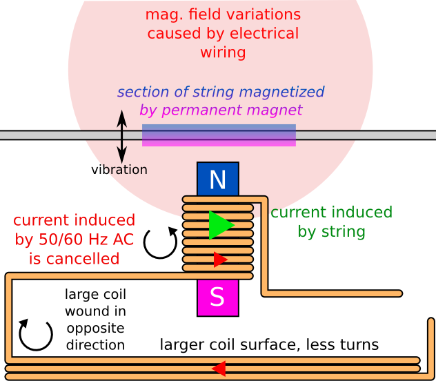
Here is an illustration (seen from the side):
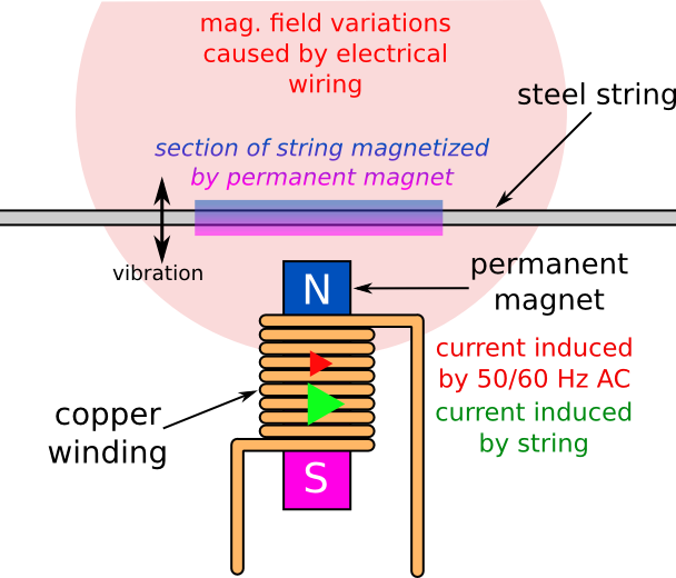
Now comes the problem, the coil acts as an “antenna” which picks up magnetic field variations. This includes the ones caused by string vibrations, but also a lot of others. The AC supply is also a source of magnetic field variations. The electric current flows alternating at 50/60Hz. The wiring forms a sort of giant coil that generates magnetic field variations following the alternative current (see Ampere’s law for details).
Since 50/60Hz is in the audible range, it causes the infamous hum that a lot of people want to get rid of.
Shielding the guitar electronics will only protect from electrostatic interferences. In order to protect against such low frequency magnetic interferences, you would need to put the pickup into a very thick iron or steel casing. But that would also protect it from the string’s vibrations, negating its purpose.
Important facts
The inductance (in Henries, or H) of a coil is proportional to the number of turns and the shape and material of its magnetic core. More inductance = higher output & darker sound, less inductance = lower output & brighter sound.
The DC resistance (in Ohms or Ω) of a coil is proportional to the number of turns and depends on the wire section. Thinner wire means more resistance per turn, thicker wire means less resistance per turn. Most pickups are wound with AWG 42 wire (except tele neck pickup which use finer AWG 43 wire). More resistance causes dampened and darker sound, less resistance causes livelier and brighter sound.
The quantity of hum picked up is proportional to the surface of the coil and the number of turns:
hum_factor = area_of_coil * number_of_turns
See Faraday’s law for more details.
How to get rid of the hum
In a nutshell, all viable solutions use the same principle. A reverse wound coil that picks up hum in opposite phase.
I will cover the most common solutions each with its implications. I know there are other hum-free pickups (Zexcoil, Fluence, etc.) which look interesting but I will not cover them here.
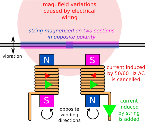
Humbucker pickup
Patented by Seth Lover in 1955 for gibson, the principle is to combine two single coil pickups wound in opposite directions with reverse polarity magnets. When these 2 pickups are next to each other, they are exposed to the same amount of 50/60Hz interferences but the induced current in each coil is reversed because of the opposite winding. When the coils are connected in series (or parallel), the “hum” currents cancel each other:
hum + (-hum) == 0
The string being magnetized in reversed polarity by both pickups, it induces currents that add up in both coils:
string + (-(-string)) ~= 2 * string
Example: http://www.seymourduncan.com/pickup/59-trembucker
There are some implications:
- The guitar must be routed specifically for humbuckers.
- The output level is almost doubled compared to a single coil pickup.
- Since both pickups cannot be at the same physical position, they do not pick up the same portion of the string. This produces comb filtering, same as when recording an instrument with two microphones that are not placed carefully.
- The electrical properties of 2 coils in series (or parallel) are very different that the ones of each coil taken separately. In series, resistance and inductance are doubled, in parallel, they are halved. This significantly changes the frequency response of the system.
- These implications are not necessarily bad. It just means that a humbucker does not sound like a single coil. Whatever the wiring.
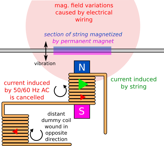
Single coil pickup + dummy coil
This is almost the same as a humbucker but one of the coils does not have a magnetic core and is moved away from the string so that it does not pick up the strings vibrations and only cancel the hum.
Example: http://www.cavalierpickups.com/frettech/dummy/index.html
The implications are:
- The dummy coil must fit somewhere into the electronic cavities of the guitar. This may require additional routing.
- The electrical properties of both coils are the same (same dimensions, same number of turns) so the dummy coil modifies the frequency response of the circuit in the same way than a humbucker.
- The dummy coil does not pick up the strings vibrations, so there is no comb filtering.
- The output level is comparable to a single coil pickup, a little lower considering the DC resistance of the dummy coil.
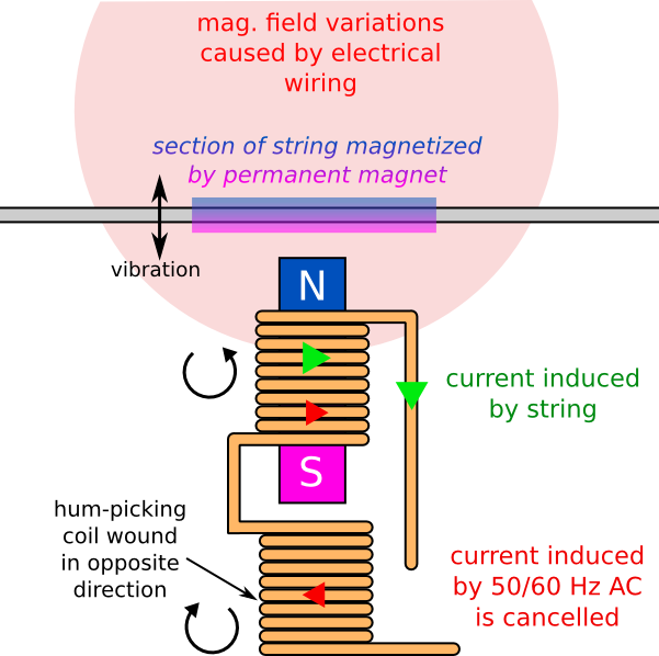
“Noiseless single coil” pickup (a.k.a. stacked humbucker)
Again, same principle, but the dummy coil is placed under the string picking coil to preserve the single coil size.
Implications:
- No modification is required on the guitar as the single coil format is preserved.
- As for the dummy coil, there is no comb filtering.
- The electrical properties of the hum picking coil modify the frequency response of the system. There may be tweaks to reduce that influence by making its area larger than the string picking coil to be able to reduce the number of turns. However, the area cannot exceed the single coil format.
Large noise-picking coil
This solution is almost similar to the dummy coil but it makes use of the fact that the quantity of hum picked up by a coil is proportional to its area and number of turns. This means that if you increase the surface of the coil, you can reduce the number of turns. Less turns means less inductance and less DC resistance, thus less electrical perturbations of the circuit.
That idea was patented by Ilitch S. Chiliachki. It has been used for over 10 years in Suhr guitars and is now sold by its inventor (see http://www.ilitchelectronics.com).
Example: http://www.ilitchelectronics.com/pgncs-t/
Implications:
- Modifications are required in order to fit the large coil. Either by routing the body or by modifying the pickguard/control plates.
- If the coil is large enough, the number of turns will be small enough to make its effect on the circuit negligible.
- There is no comb filtering.
- The output level of the single coil pickup used with the large coil is not altered.
- There are hundreds of good sounding pickups that have been here for decades. This last solution is the only one that allows you to keep the pickups that you like but without the 50/60Hz hum.
Specifications
Before going further, we need to know where the coil will be fit into the guitar. Ilitch manages to put it into the pickguard or tremolo back plate. This is extremely delicate work and I don’t have the tools nor the skills to do it. This also forces to use finer wire to make the coil smaller. Finer wire means more DC resistance.
I chose to place it under the pickguard of a strat. This can also be done for a tele.
First thing to do is determine a shape for the coil. The goal is to maximize its area. I did not try to be inventive here and chose the same shape that the ilitch PGNCS-S:
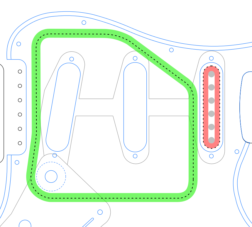
Keep in mind that the coil will have a certain thickness and depth which are hard to estimate before the winding is done.
Now that the shape is settled, let’s calculate its area based on the center of the coil windings. Since I am lazy, I used software to do that for me. But you could calculate it by hand by splitting it into simple areas (squares, rectangles and discs).
large_coil_area = 0.01475 m²
Note that I am using square meters here (because I am french and to also annoy US people, but mostly because I am french) but the unit does not matter. You may calculate it in square inches or acres as long as it is correct.
Then, I calculate the number of turns of my pickup along with its area.
Important note here: Since the pickup has a magnetic core and that the large
coil does not, the rule hum factor = area * n° of turns is not completely
exact. The pickup will have slightly higher hum sensitivity due to the
increased inductance from the magnetic core. Since I don’t know how to
calculate that, I chose to calculate the pickup area based on the outer
dimensions of its coil (not the center). That “should” compensate for the
influence of the magnet.
pickup outer perimeter = 0.1447 m
pickup outer area = 0.00080279 m²
pickup DC res. = 6900 Ω
AWG 42 wire DC res. = 5.446 Ω/m

pickup DC res. per turn = perimeter * DC res per length
pickup DC res. per turn = 0.1447 * 5.446 = 0.7882 Ω

pickup turns = pickup DC res. / pickup DC res per turn
pickup turns = 6900 / 0.7882 = 8754 turns
Using the fact that hum factor = number of turns * area and that we want both
coils to pickup the same amount of hum, we get
large coil turns = pickup turns * pickup area / large coil area.
pickup hum factor = turns * area
pickup hum factor = 8754 * 0.00080279 = 7.03

large coil turns = hum factor / large coil area
large coil turns = 7.03 / 0.01475 = 476 turns
Mind that this number is not accurate with the approximations I made. If it is too high, I’ll be able to fine adjust the hum reduction with a trim pot, I just hope that it is not too low.
The patent by Ilitch describes the schematic used to blend in the large coil. It is basically a tone and volume pots with a tone capacitor. The idea is to avoid the large coil to bring too much high frequencies which would cause flange noises when blended with the pickup. Since the hum is 50/60Hz (with some harmonics), I decided to omit the tone pot.
Here is the schematic I will use:
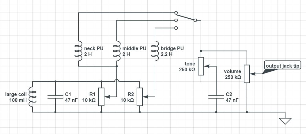
R1 and R2 will be used to adjust the amount of reverse hum blended into the circuit (R1 for the neck/middle and R2 for the bridge pickups). It is important to note that all pickups must be wound in the same direction for this thing to work.
Building
First, I need to know the winding directions of my pickups to wind the large coil in the opposite way. My pickups are Suhr V60LP with regular middle (non RWRP). They are wound clockwise (when looking from the top of the guitar). So I will wind the large coil counter-clockwise.
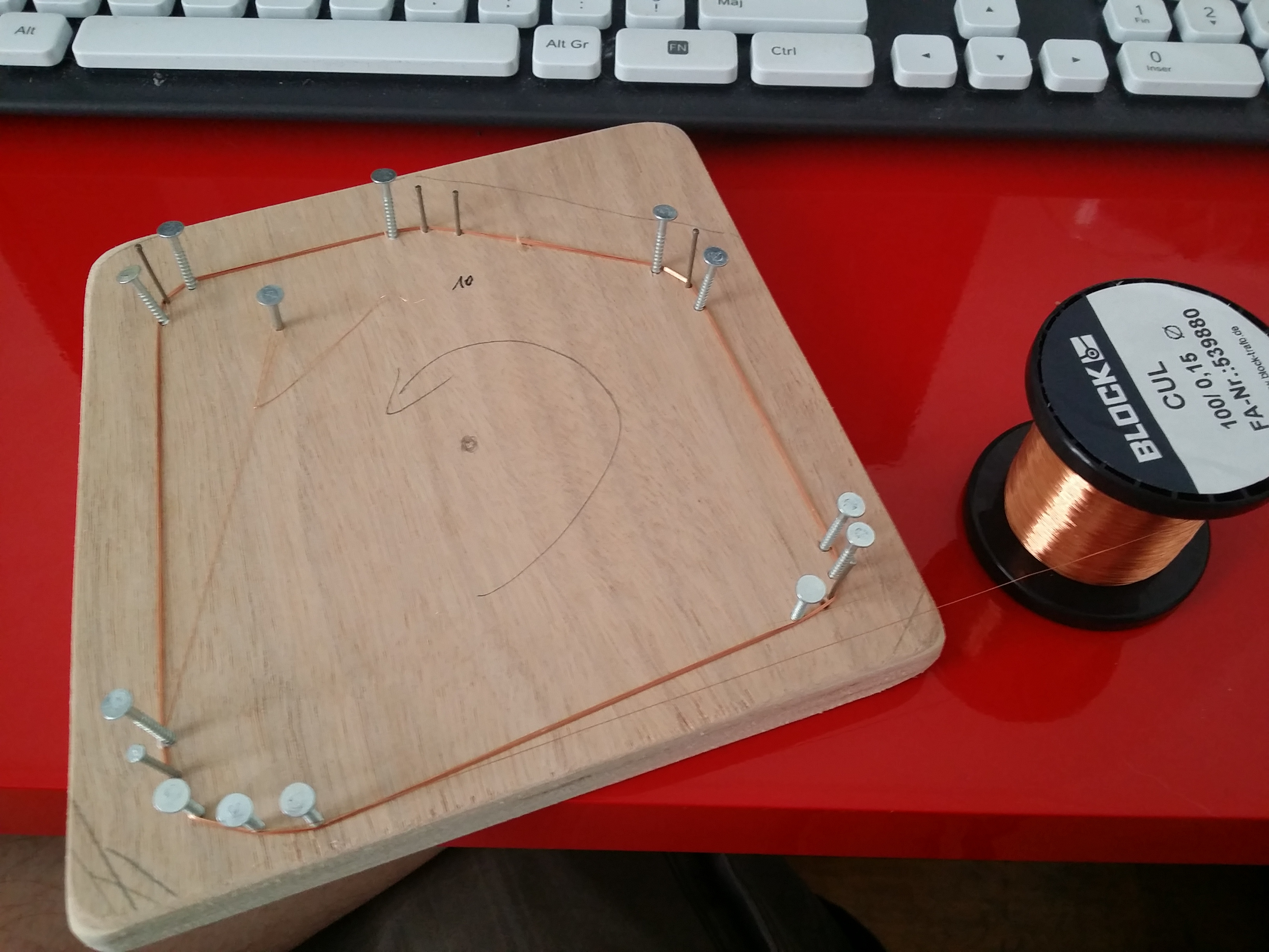
I chose to use bigger wire to reduce the DC resistance of the coil. The wire has 0.15 mm diameter which is between AWG34 and AWG35.
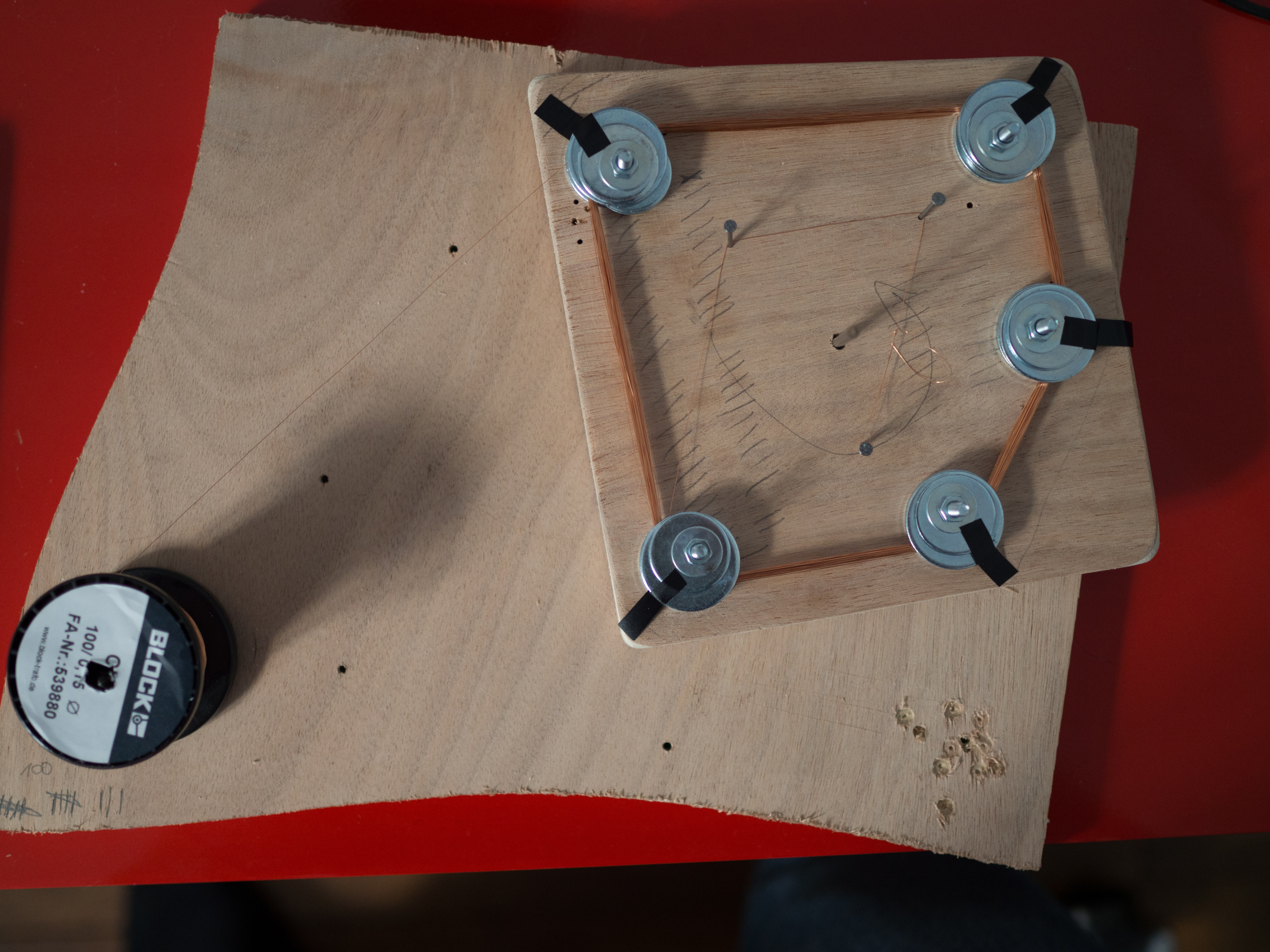
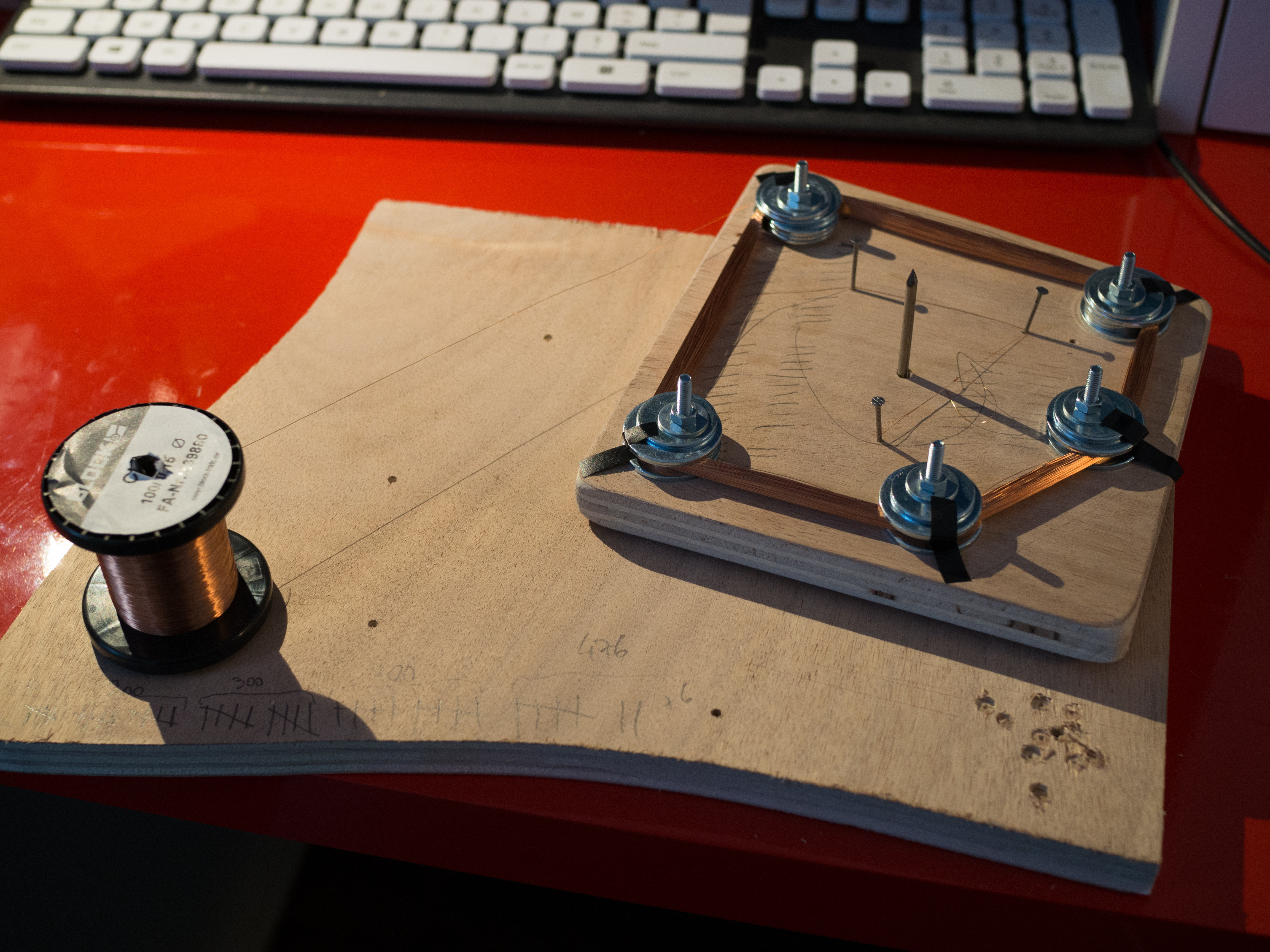
Then, I need a sort of flat work winding jig that I can tear down once the coil is wound. My first attempt with nails in a piece of plywood scrap was not satisfying as I could not control the coil’s thickness:
I have opted for another solution using big-ass washers and some gaffer tape:

Here all 476 turns are done, that went quicker than expected (about 30 minutes)
I measured the coil DC resistance to 220 Ω. That’s more than 31 times less than the bridge pickup! I have no way to measure the inductance but I figure it is quite low.
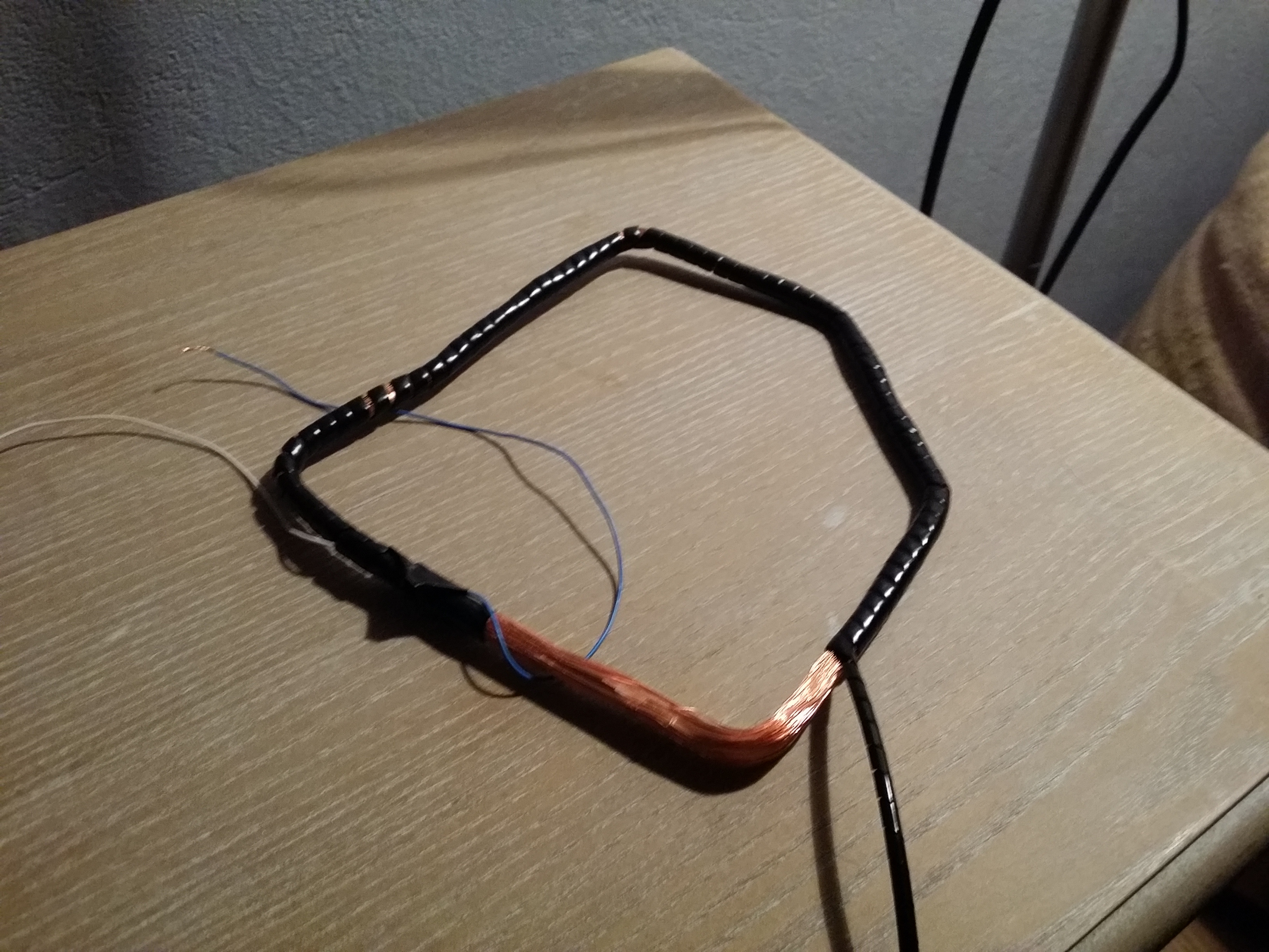
Before tearing down the winding jig, I put some drops of CA glue in strategic places to avoid the coil to unwind itself. I also took the opportunity to solder 2 insulated wires to both ends of the coil.
Once the coil free, I wrapped it with spiral tubing to protect it.
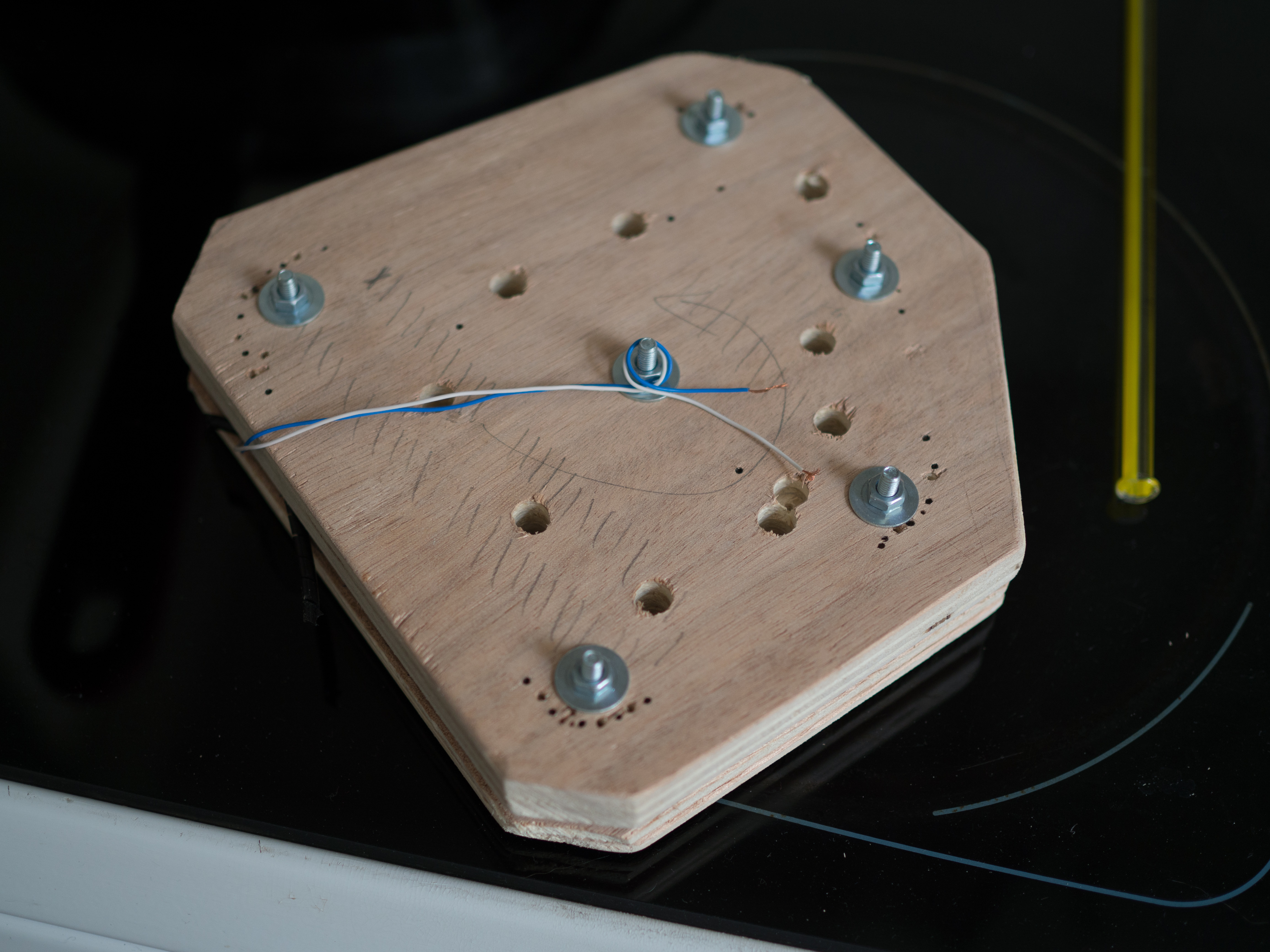
I chose to wax pot the large coil to reduce micro phonic noises. For that I reused my winding jig to make a wax-potting press.
Then, I went to the hardware shop and bought 500g of paraffin, put it in an old saucepan which I heated with boiling water (to avoid putting myself on fire). I made sure not to heat the paraffin over 80°C (~175°F).
I put the coil into the paraffin for about 1 minute (until I didn’t see any air bubbles coming out) and voilà:
I am pretty happy with the result, the coil is about 4 mm thick. It is not too much wood that I will need to remove from the guitar.
I did not have a routing bit with the bearing on top so I only made a template to avoid going too much outside the channel.
The routing was made on the fly following the drawing on the body:
For my first time with a router, things could have gone worse.
I bought a prototyping PCB (I may also use the ones with tracks but the layout will be different), two 10K trim pots, a 68nF capacitor and some colored wire (to make it look professional). I cut a segment of the PCB with a hack saw and soldered the schematic. Everything was packed on a 20x30 millimeters board.
Unfortunately, I could not find any of the pictures that I had taken.
The large coil was installed under the pickguard and held in place under the pickups screws and some of the volume pot wires.
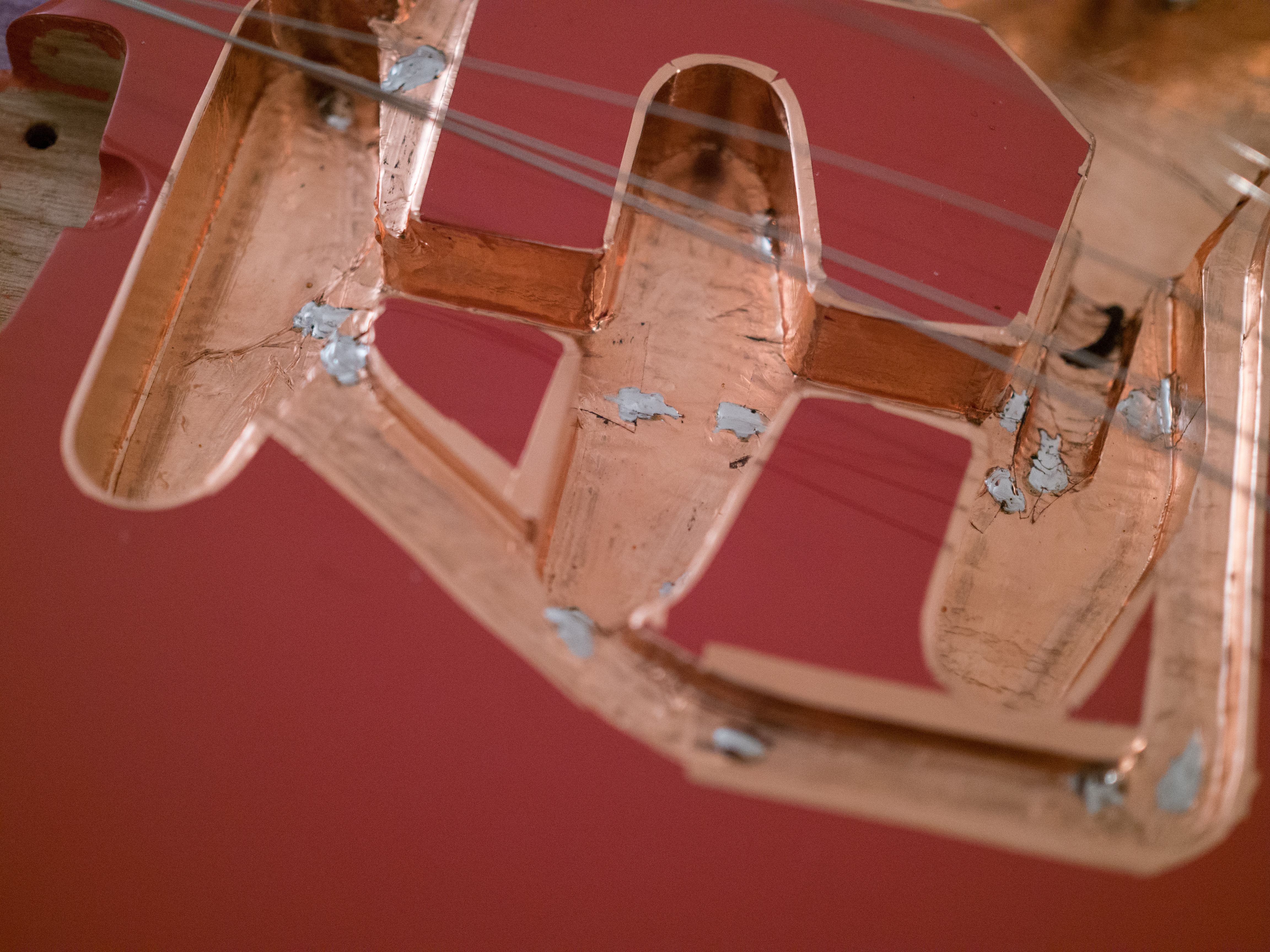
The last pictures I have of the “electronics” are when I did install the copper shielding in the guitar body.
Tests & conclusion
Here are some recordings I made with the system installed on a strat.
Unfortunately, I don’t have an audio interface with microphone inputs at the moment. So I had to record through my Line 6 POD xt. The guitar tone itself is crappy but what matters is the differences between with and without the system enabled.
Here is the setup:
Guitar -> 3m lava cable -> POD xt -> USB cable -> computer with reaper
I dialed basic sounds on the POD to get a basic idea of what it sounds like through a real amplifier. Both clean and dirty tones.
There are 2 clean clips and 2 dirty clips. Each one of them recorded 3 times:
- with the system disabled (hum)
- with the system enabled and a 56nF cap in parallel with the large coil (no hum)
- with the system enabled and no cap in parallel with the large coil (no hum no cap)
To enable/disable the system, I used the trim pots. Fully counter clockwise to short circuit, clockwise to cancel hum.

Please excuse my approximate playing…
Here are my observations:
- After testing, I noticed a little less noise (not hum, high freq noise) without the filtering capacitor. I chose to remove it at the last minute.
- The system completely cancels hum on the bridge pickup. This one is dead silent.
- Although it remains far lower than without the system. The noise becomes gradually more present on the middle and neck pickups. I don’t know why. This could be because of the trim pots, or bad shielding.
- Also, when I roll off the volume a little (between 9 and 7) the hum seems to resurface and then disappear again past 7. I only noticed this after removing the cap from the circuit. I have no idea if that was present before or if it is related. This also could be because of the trim pots.
I hope this was helpful.